35-105mm f/3.5
This guide provides step-by-step instructions for disassembling and reassembling a Canon 35-105mm f/3.5 lens.
Disclaimer!!!
This lens is not officially supported.
This guide is user-generated and requires modifications to the conversion kit in order to be compatible with this lens.
As a result, this guide does not contain original images of the Canon 35–105mm f/3.5. Instead, images from other lenses have been borrowed for reference. Because of this, certain steps may be inaccurate—or the entire guide could be completely wrong.
No modifications will be made to the lens itself. Only the conversion kit will be altered (by sanding or filing certain parts). This conversion kit process can be reset to its factory condition, which, of course, ensures that your existing lens warranty remains intact.
Step 0: Requirements
Lens, Triple zero Phillips screwdriver, Plastic Prytool (Or equivalent) In addition to the Standard gear required this guide requires a file and or sandpaper
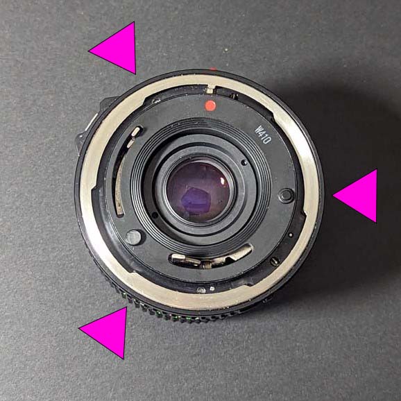
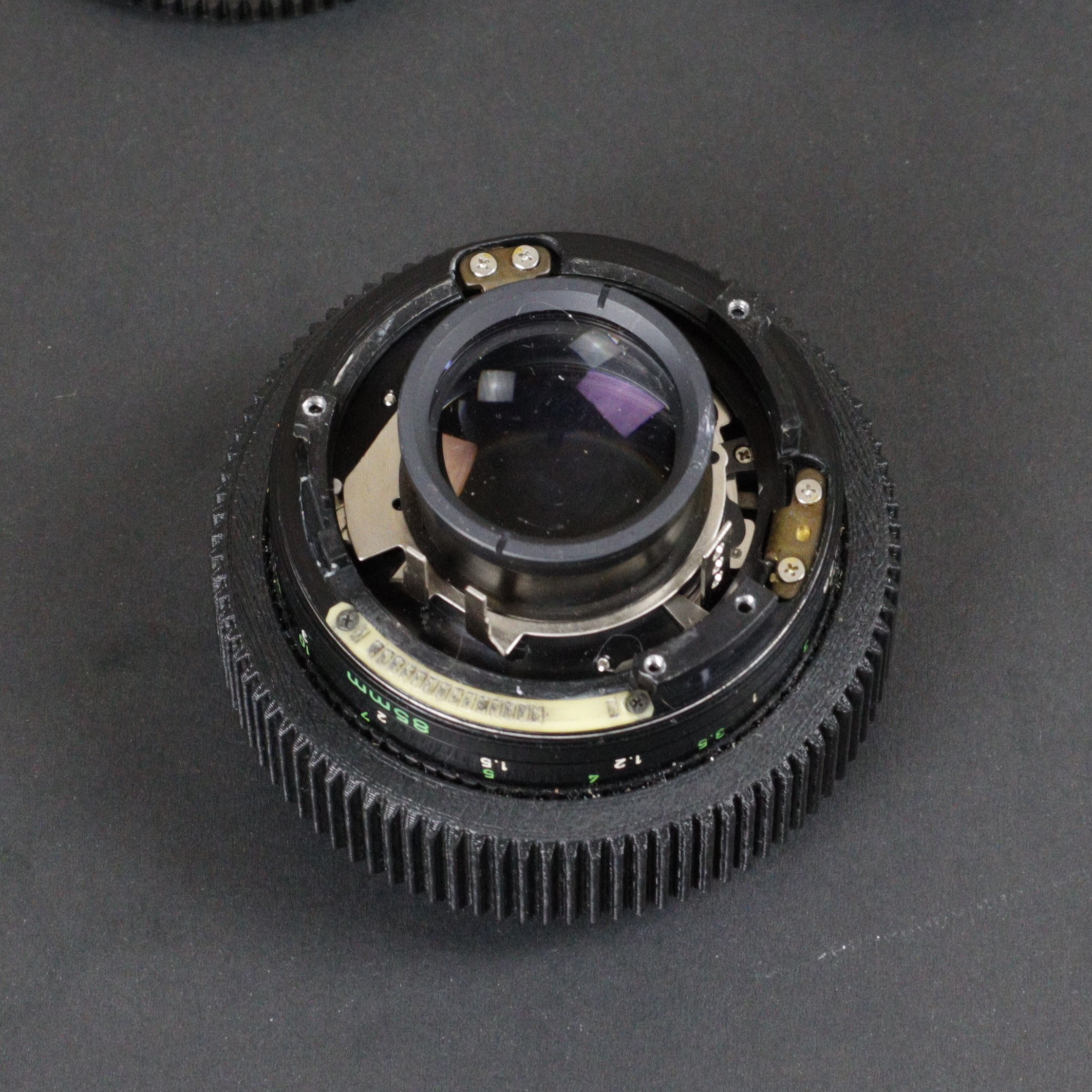
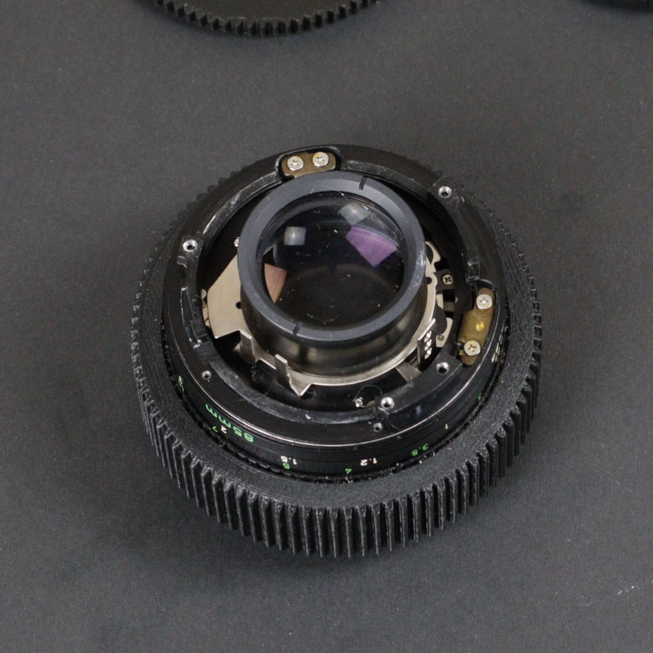
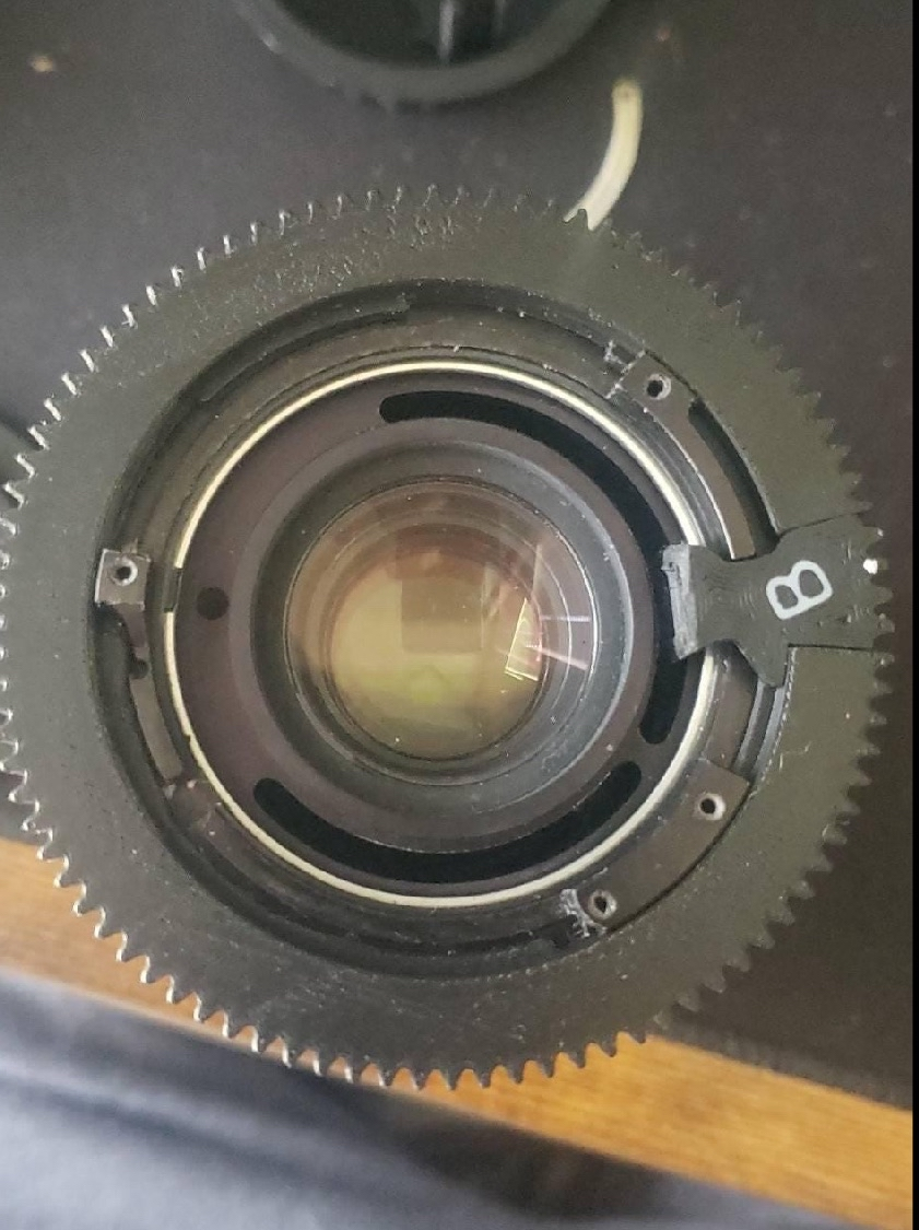
Step 1: Remove Screws
Remove the three screws outlined in the image.
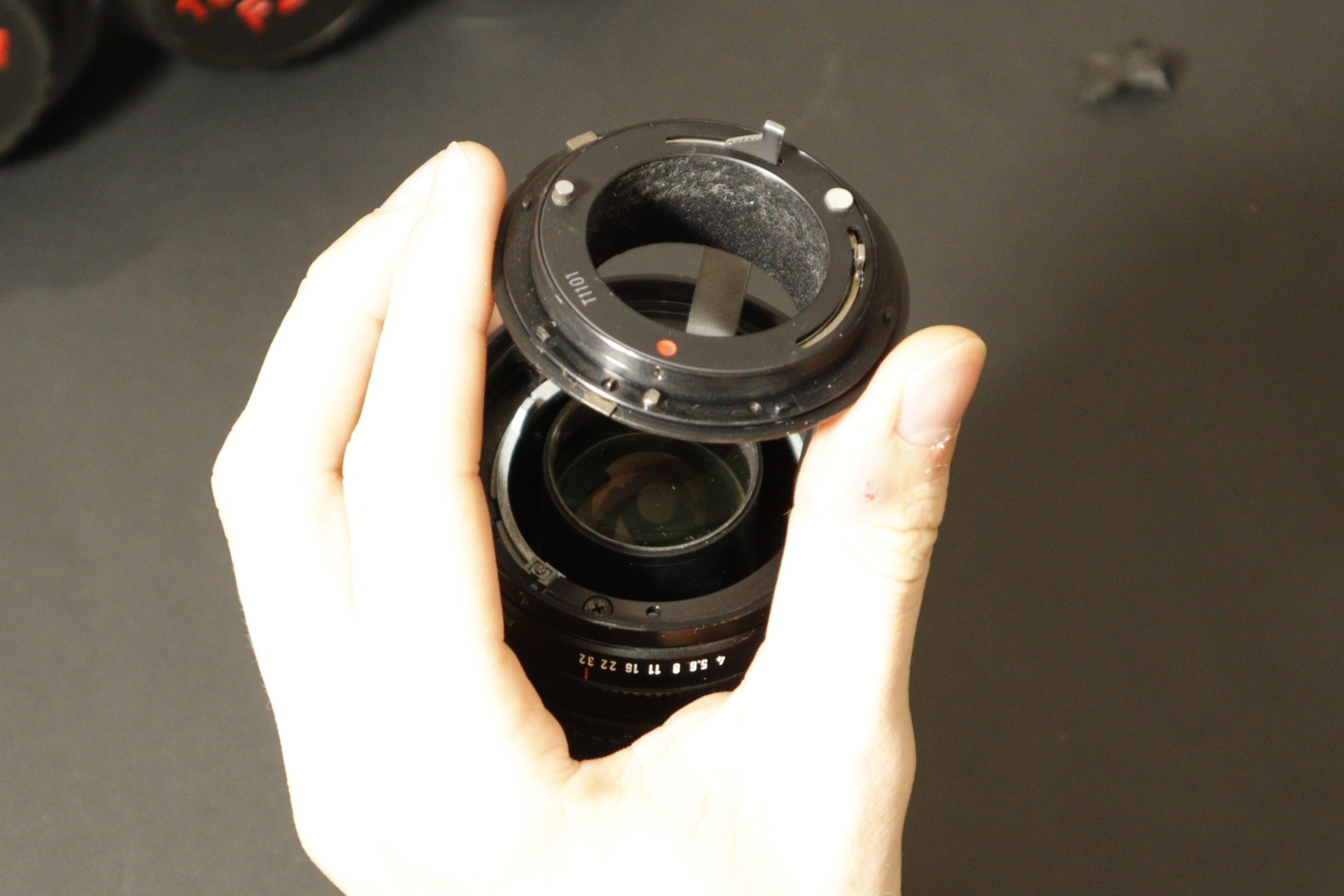
Step 2: Remove the retaining ring
Note the image from the 28mm F/2.8 guide. It will look the same.
Gently circle around the ring, prying it up a small amount. These parts are not needed for the conversion kit, but if you would like to put them back together, proceed cautiously.
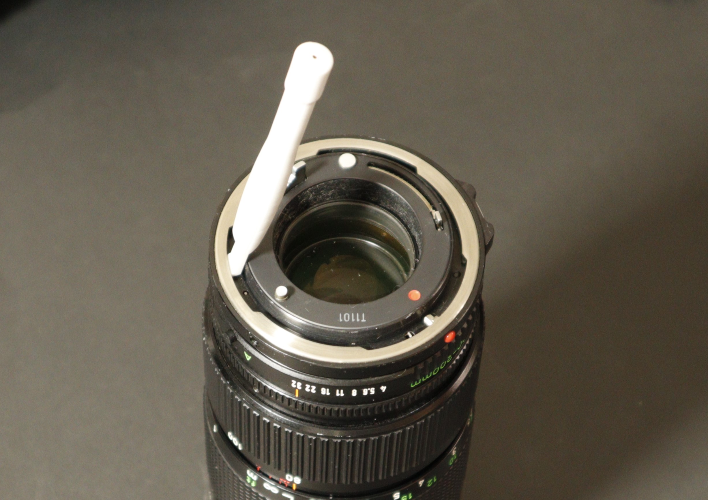
Step 3: Remove Aperture Control Interface
Note the image from the 80-200mm f/4 guide. It will look the same.
Pull up with an orthodontal twisting motion, as this piece is under spring tension.
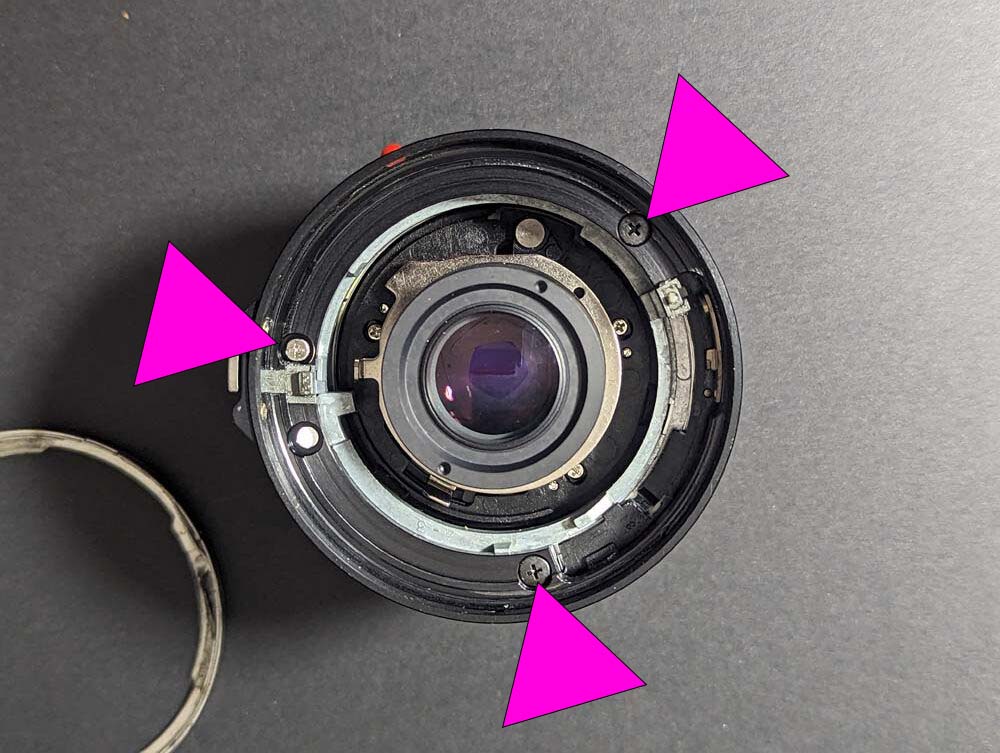
Step 4: Remove three screws
Remove the four screws and keep them safe for reinstallation. Note that the image depicts three screws; however, the 85mm f/1.8 lens has four screws.
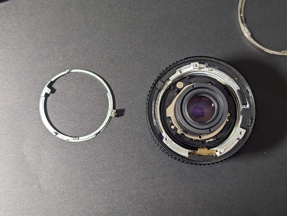
Step 5: Remove Inner Aperture Control Ring
Note the image from the 28mm F/2.8 guide. It will look the same.
Carefully remove the inner aperture control ring. This part can be difficult to remove. Ensure to apply even pressure upwards away from the lens. Tilting it may cause damage to this part. These components are not required for the conversion kit, but if you wish to reassemble them, proceed with caution.
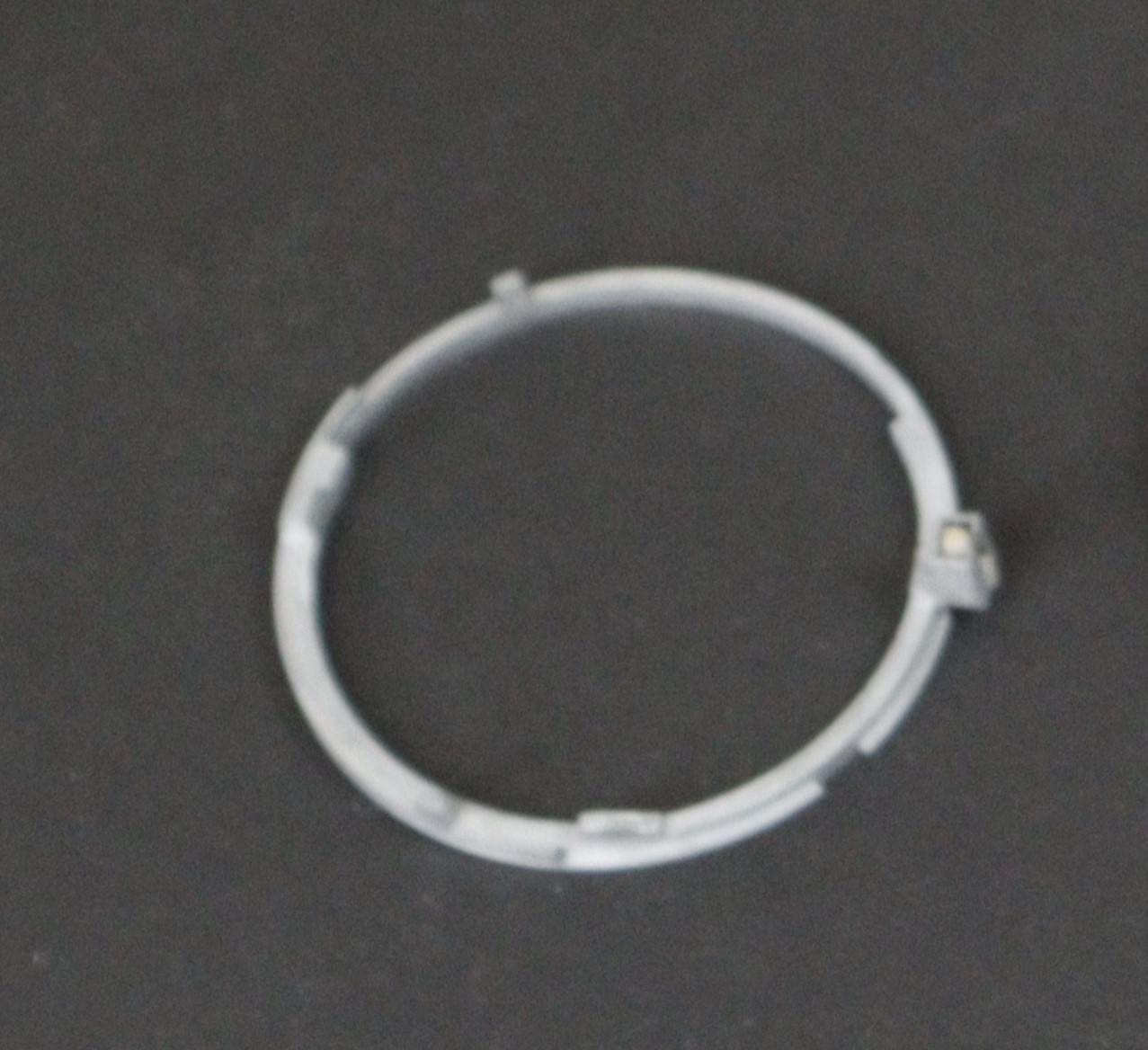
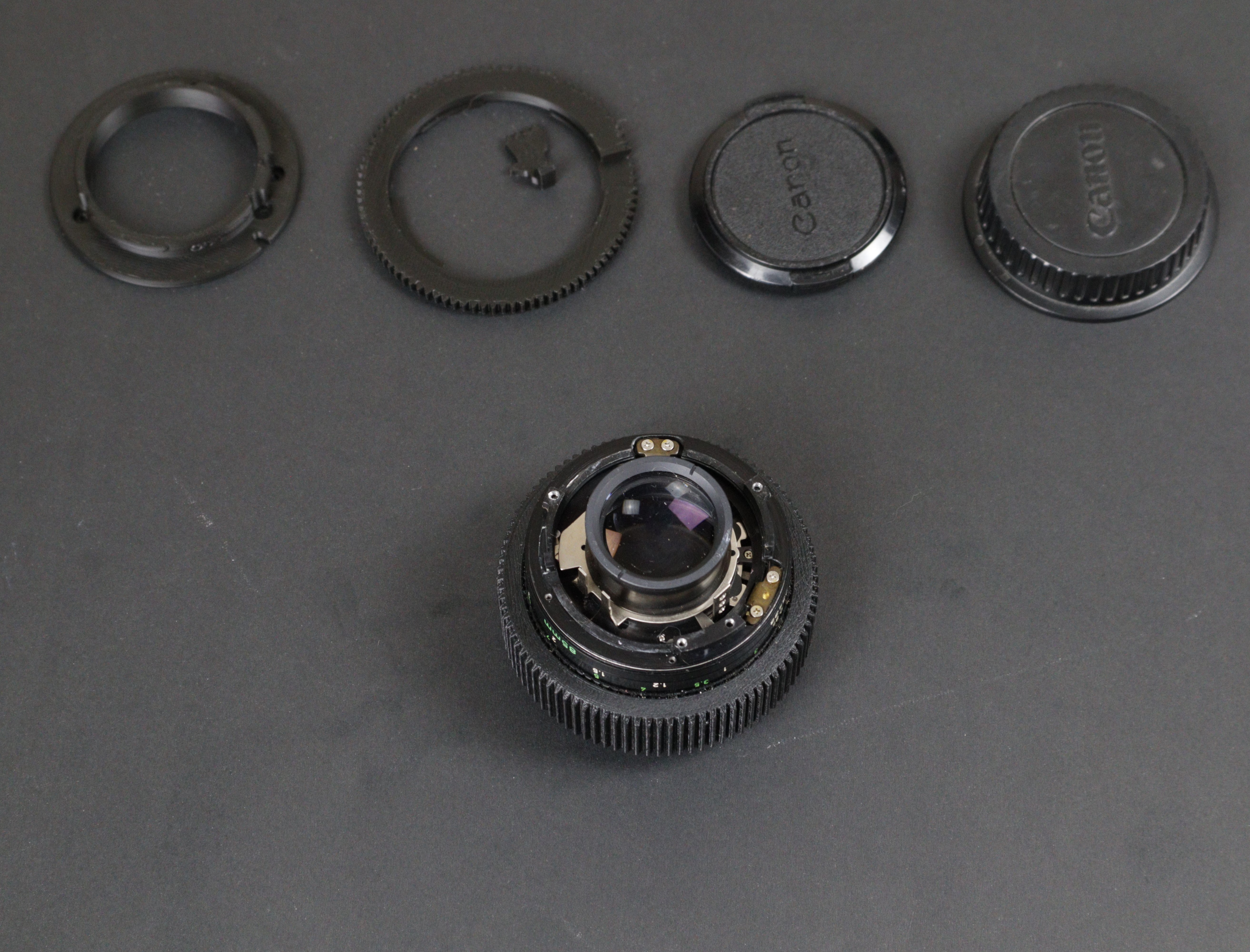
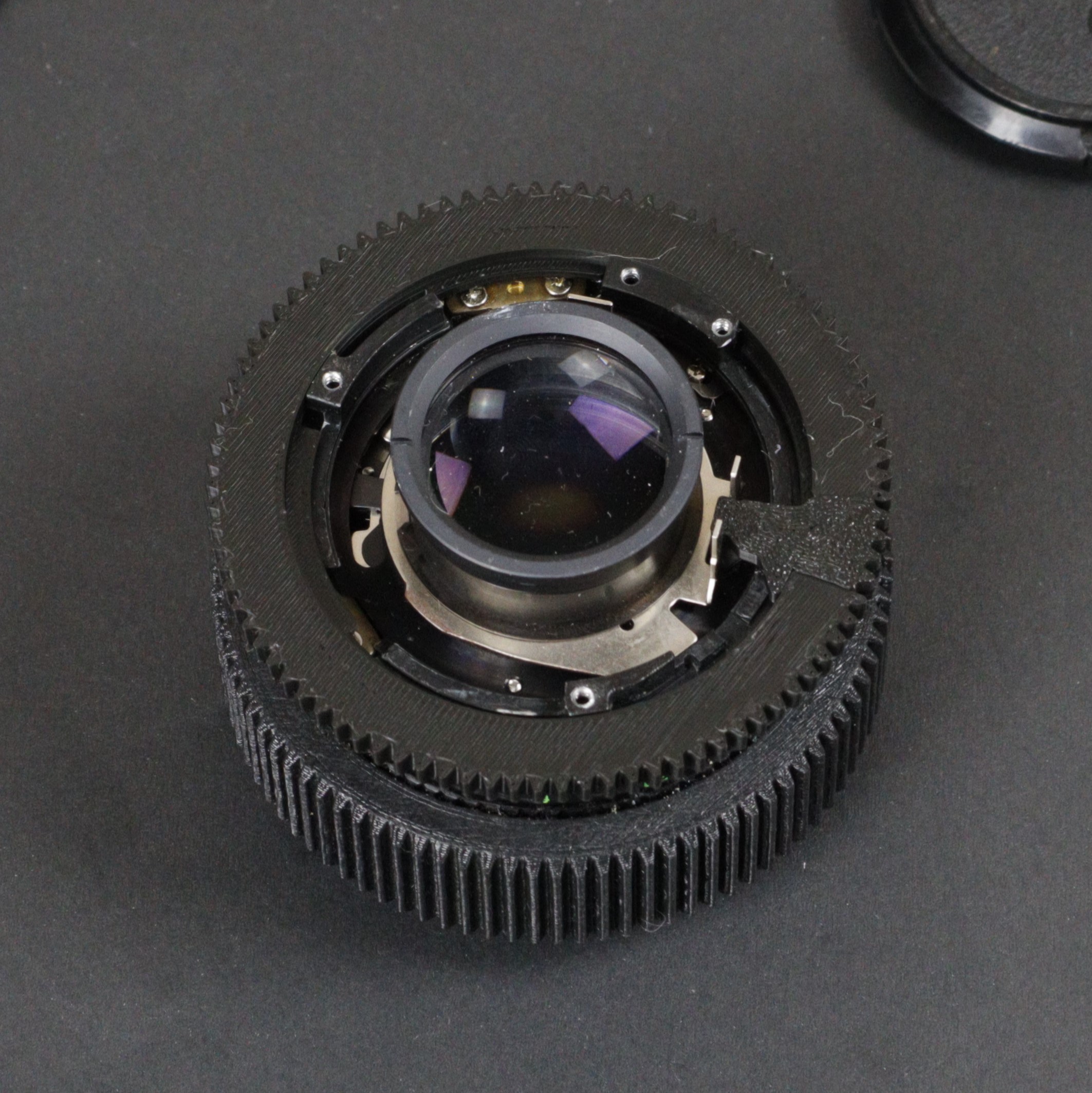
Step 5.1: Image of the inner aperture ring.
This is a zoomed picture of the inner aperture ring.
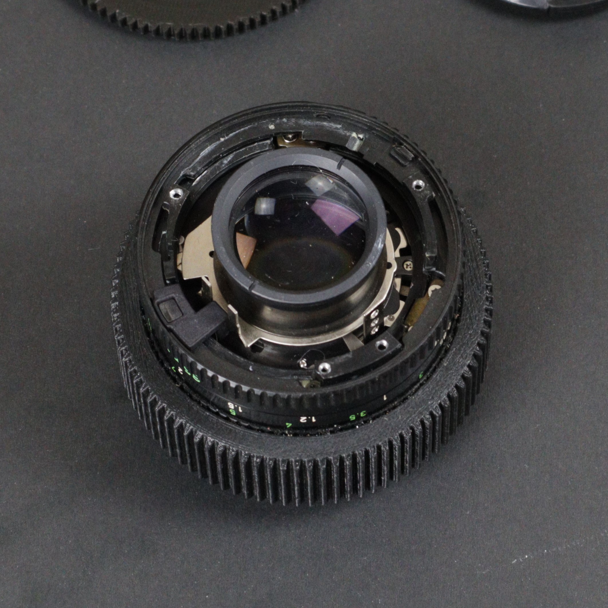
Step 6: Remove the outer aperture control ring
Remove the outer aperture control ring.
Step 6.1: Cautioned small parts
Pay attention to the automatic lock and aperture click detent They are friction fit And can be easily lost .!
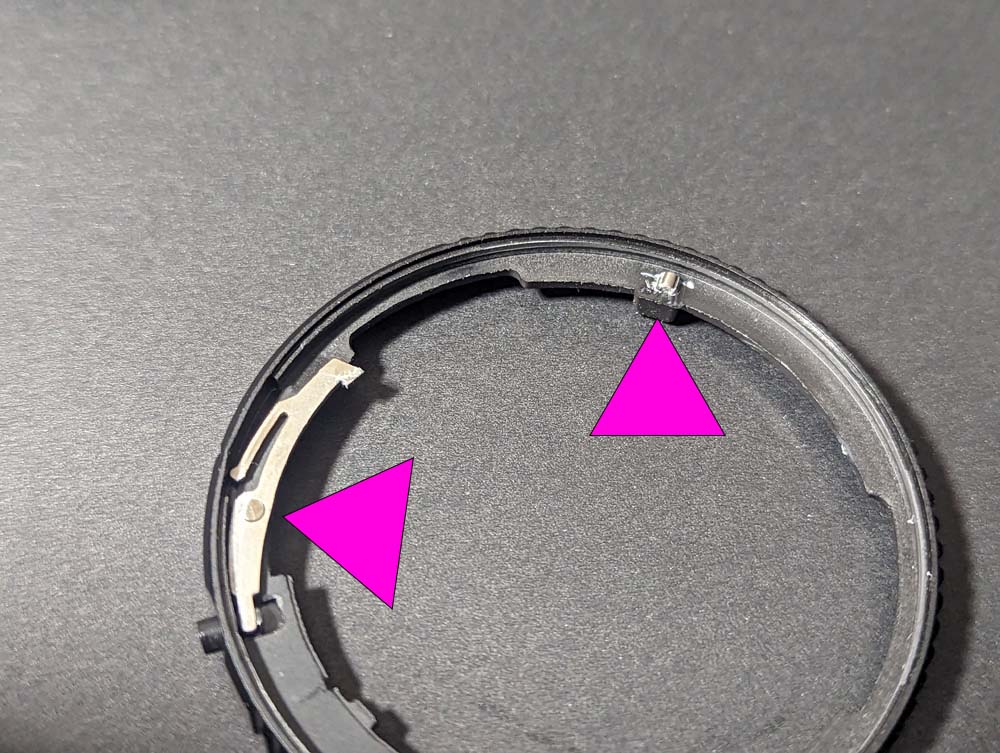
Step 7: Remove screws for aperture control click
Remove these two screws for the aperture control click.
Step 7.1: Remove screws for aperture control click
After removal of the click control
Modification time!
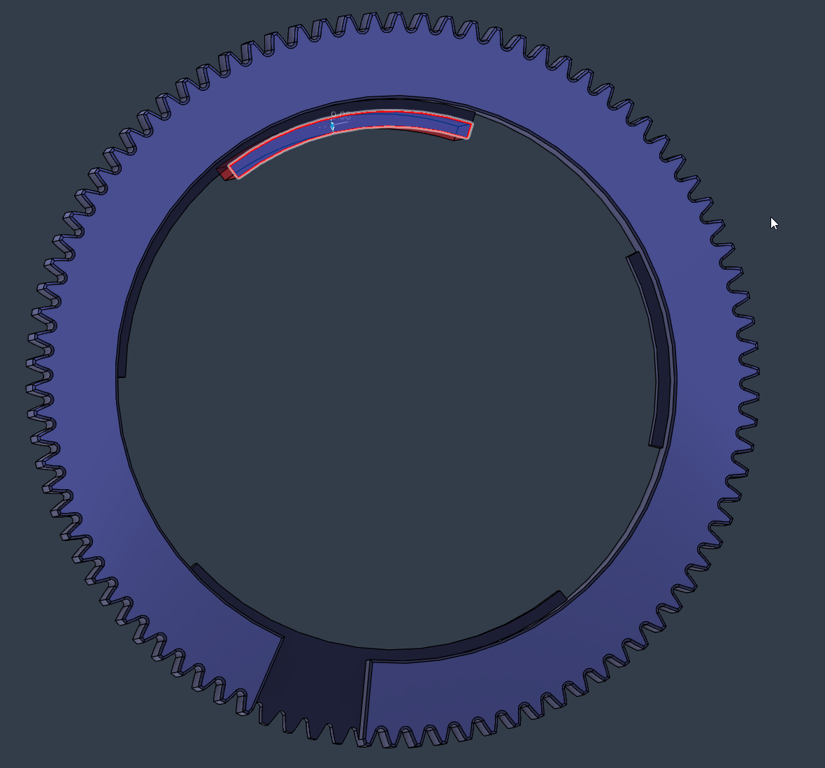
Geared Aperturing Modification
The image for this step highlights an additional red-marked area that must be removed. The inner surface of the geared aperture ring has multiple steps of varying diameters, and this lens is incompatible with one of them.
Carefully remove the red-marked step from the geared aperture ring as shown in the image..
Recommended tools: a fine file, or sandpaper wrapped around a dowel..
On most lenses, this step prevents the follower on the aperture control cam from over-rotating. However, this lens already includes features that prevent over-rotation. In this case, the step interferes with the aperture mechanism and limits the full range of motion of the blades. Removing it restores proper operation.
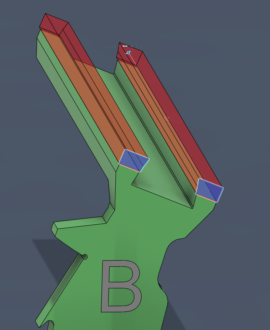
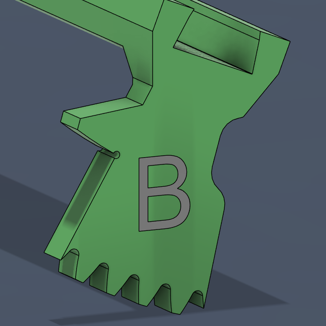
B key Modification
The image shows the B key in its complete form, with one side highlighted in transparent red. The red portion indicates the material that needs to be removed..
Carefully remove the red-marked section of the B key, reducing its overall width by approximately 1.5 to 2 millimeters so it will fit into the lens slot..
Recommended tools: sandpaper on a flat surface (120 grit or higher)..
This part was designed thicker for structural strength, so take your time and check the fit often. Be mindful that plastic dust is harmful to the lens mechanism—it can cause grinding and affect smoothness. Wipe the part clean with a damp cloth before each test fitting.
Modification complete
Thank you to Lester For providing this info and this image
Reassembly of the lens
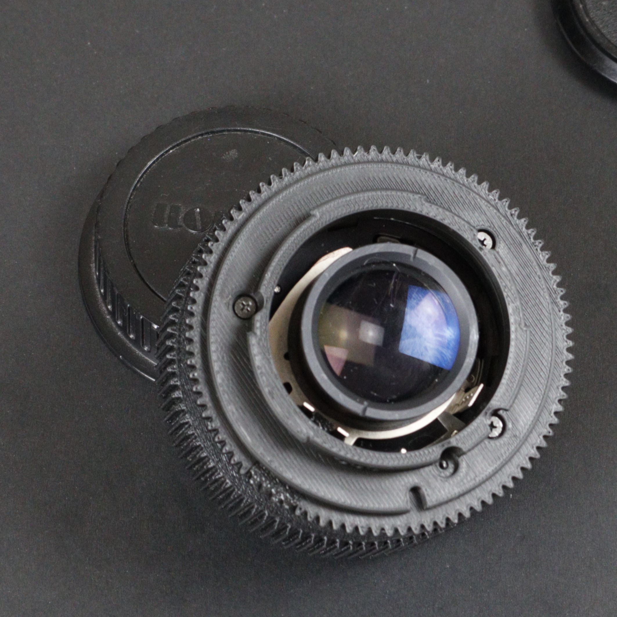
Step 8: Install gear aperture ring
Put the gear aperture ring on the lens. Ensure it fits properly without forcing it, aligning it with the middle peg on the iris.
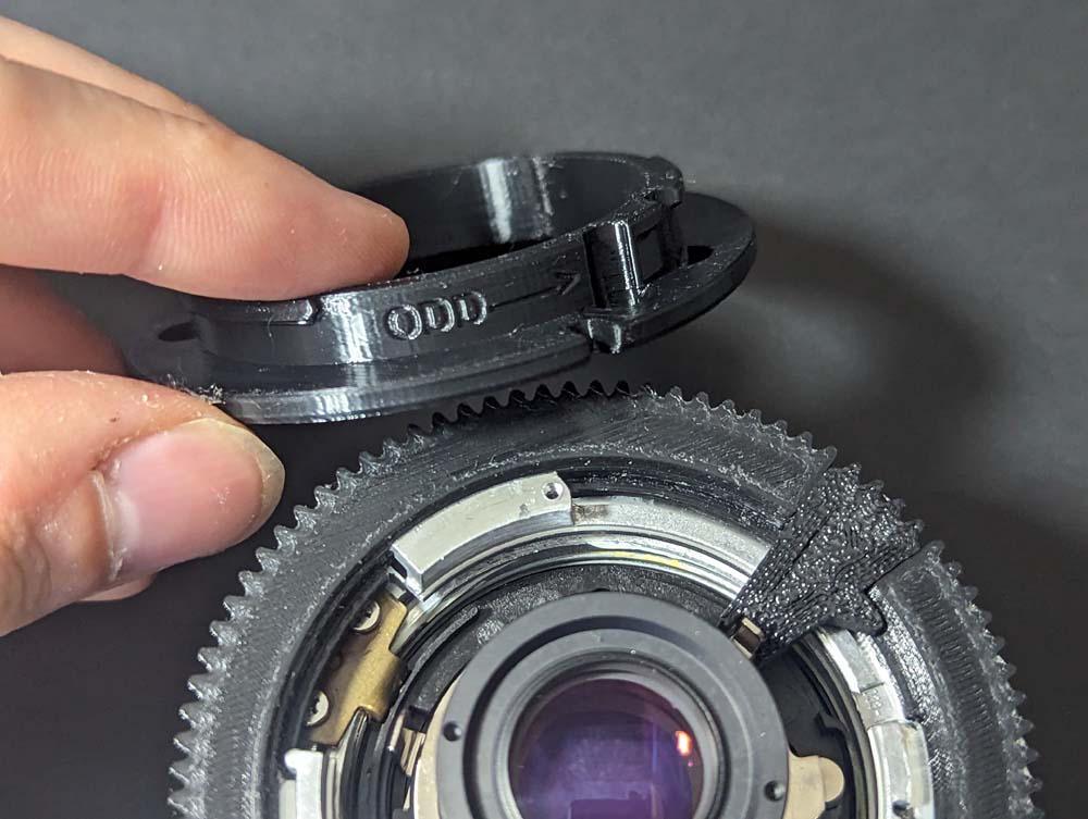
Step 8.1: Use the B key
Install the B key in the aperture control ring. The letter should face upwards, away from the lens. Align it between the two prongs of the lens aperture control ring.
Step 9: Install EF lens mount
Note: The animated image is from the 50mm f/1.8 guide and will look similar.
Align the screws as indicated in the GIF. The silver screw goes in the spot labeled as 'odd'. All four screws should be installed.
Step 9.1: Attach EF Lens Mount
If the holes do not line up, rotate the lens mount 60 degrees or until the next hole aligns. Not all hole spacings are the same. There is only one correct way that this fits on.
Step 10: Assembly complete
Assembly is complete. Enjoy!